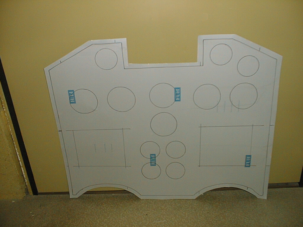
I found some stereo MHz meters at a local electronic store. As they has a wide movement (250°) I thought that they would do as engine instruments
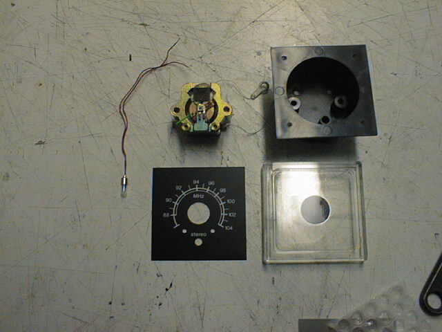
This is how it looks when dismantled
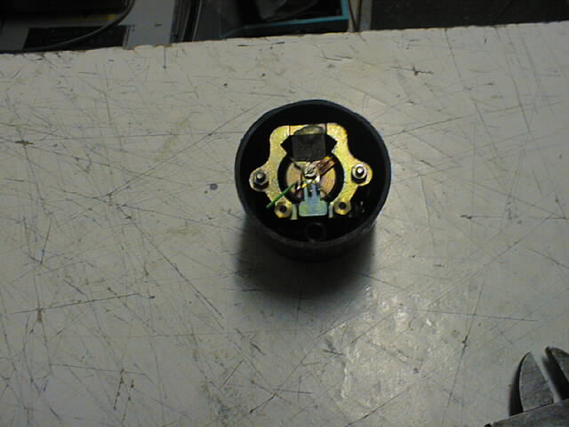
After I had trim off the frame this is remaining
Dials made of paper, printed on laser, colors added by hand when needed
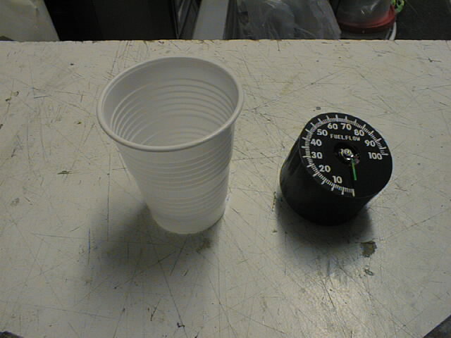
To get space enough for needle to go clear from glass, I used plasic cans, cut to suitable size and glued to place. I use fast cure CA glue
This is how it looks when assembled. As the plastic can is semi-transparent, light will shine up the dial and needle when a lamp is added behind the instrumentpanel
Same instrument from another angle
Glass made of 1mm Plexi and glued to distance. Used epoxy to prevent damage to glass.
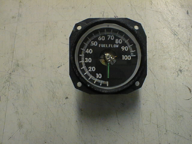
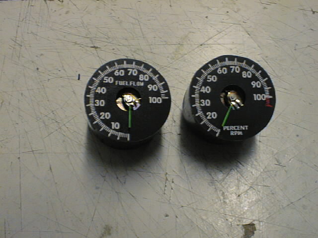
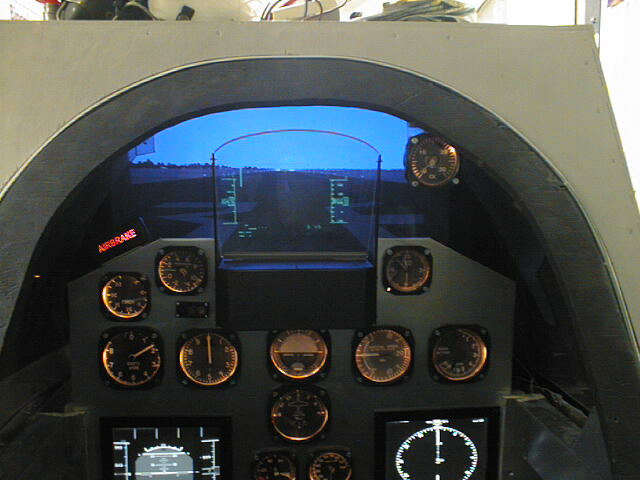
Final assembly with my gauge faceplate. Instrument is 0 at 0Volts and 100% at 10Volts